(A) Atomic structure of calcium titanate (GaTIO3) crystal; (b) Atomic structure of methamine lead iodide (CH3NH3PbI3) crystal in the light-absorbing layer of perovskite solar energy.
High photoelectric conversion efficiency
To understand the secrets of perovskite solar cells high-efficiency performance and favored by people, we have to talk about its light absorption and energy conversion principles.
Schematic diagram of exciton generation
This wonderful process is roughly as follows:
Sunlight is absorbed immediately after being incident on the battery absorption layer, and the energy of the photon excites the electrons originally bound around the nucleus to form free electrons.
Since the substance as a whole must remain electrically neutral, when the electron is excited, an additional positively charged counterpart will be produced at the same time, which is called a hole in physics. Such an "electron-hole pair" is what scientists often call "excitons".
Schematic diagram of the structure and operation mechanism of perovskite solar cells
After the excitons are separated into electrons and holes, they flow to the cathode and anode of the battery, respectively.
The organic metal halide perovskite structure solar cell is a kind of solar cell using an all-solid perovskite structure as the light-absorbing material. Its energy gap is about 1.5eV and the extinction coefficient is high. A thin film of several hundred nanometers can fully absorb 800 nm. The following sunlight has important application prospects in the field of photoelectric conversion. Perovskite solar cells are known as "a new hope in the photovoltaic field" due to their good light absorption and charge transfer rate, as well as huge development potential. As battery efficiency records continue to be refreshed, more research results on perovskite batteries continue to emerge, covering various aspects of structural design, working mechanism, and optimization of preparation processes.
Basic structure and battery structure of organic metal halide perovskite
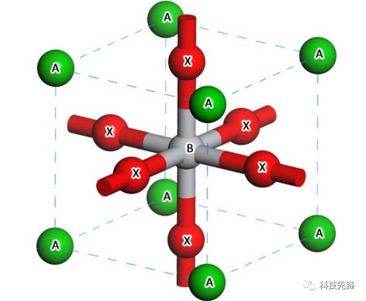
The organic metal halide perovskite structure solar cell is a solar cell that uses an all-solid perovskite structure as a light-absorbing material. The preparation process of this material is simple and the cost is low. The general structural formula of the perovskite material is ABX3, where A is an organic cation, B is a metal ion, and X is a halogen group. In this structure, the metal B atom is located at the center of the cubic unit cell, the halogen X atom is located at the center of the cube face, and the organic cation A is located at the apex of the cube (Figure 1). Compared with the structure connected in the form of co-edge and coplanar, the perovskite structure is more stable, which is conducive to the diffusion and migration of defects.

Figure 1 Schematic diagram of the structure of perovskite ABX3
In the perovskite structure used for high-efficiency solar cells, the A site is usually organic cations such as HC (NH2) 2+ (FA+ for short) or CH3NH3+ (MA+ for short). Its main function is to maintain charge balance in the crystal lattice, but The size of the A ion can change the size of the energy gap. When the radius of the A ion increases, the lattice expands, resulting in a correspondingly smaller energy gap and red shift of the absorption edge, resulting in a larger short-circuit current and a high battery conversion efficiency of about 16%. Metal ion B is usually Pb ion. Pb has good stability, but due to its toxicity, it is often replaced by Ge, Sn, and TI. Taking Sn as an example, the bond angle of Sn-X-Sn is larger than that of Pb, and the energy gap is narrower. ASnX3 exhibits high open circuit voltage and good photoelectric characteristics, with very small voltage loss. But in the same group of elements, the smaller the atomic number, the worse the element stability. In order to solve the stability problem, Pb and Sn are combined in a certain ratio to reduce the instability caused by Sn and at the same time obtain a higher conversion efficiency. The halogen group X is usually iodine, bromine and chlorine. Among them, perovskite solar cells with iodine groups are not as good as batteries with bromine groups in terms of mechanical properties (such as elasticity, strength, etc.). The electron absorption spectrum broadens from Cl to I, and the red shift of the energy gap also increases. This is because as the atomic weight increases, the electronegativity of the element becomes weaker, and the covalent effect in bonding with the metal ion B increases. ABX3 type organic-inorganic halides have different structures at different temperatures.
The basic structure of perovskite solar cells is usually substrate material/conductive glass (substrate glass coated with an oxide layer)/electron transport layer (titanium dioxide)/perovskite absorption layer (hole transport layer)/metal cathode ( figure 2).

Figure 2 (online version color) schematic diagrams of two typical perovskite solar cells.
(A) Mesoscopic structure perovskite solar cell;
(B) Planar heterojunction structure perovskite solar cell
After the incident light enters through the glass, photons with energy greater than the forbidden band width are absorbed and excitons are generated. Then the excitons are separated in the perovskite absorption layer, become holes and electrons, and are respectively injected into the transport material. The hole injection is from the perovskite material into the hole transport material, and the electron injection is from the perovskite material into the electron transport material (usually a titanium dioxide film). Based on this, perovskite has two types of structures: mesoscopic structure and planar heterojunction structure. Mesostructured perovskite solar cells are developed based on dye-sensitized solar cells (DSSCs), which are similar in structure to DSSCs: perovskite-structured nanocrystals are attached to the mesoporous oxide (such as TIO2) framework material, The hole transport material is deposited on its surface, and the three together serve as the hole transport layer (Figure 2(a)). In this structure, the mesoporous oxide (TiO2) is not only a framework material, but also can play a role in transporting electrons. The planar heterojunction structure separates the perovskite structure material and is sandwiched between the hole transport material and the electron transport material (Figure 2(b)). The excitons are separated in the core perovskite material, which can simultaneously transport holes and electrons.
The crystallographic orientation of the perovskite structure material also affects the cell efficiency. Research by Docampo et al. found that when the immersion temperature of the solution is increased, or the subsequent heat treatment is performed after mixing CH3NH3I and PbCl2, the resulting battery has a larger short-circuit current and higher conversion efficiency. The change in this process is that the long axis direction of the perovskite structure tends to be parallel to the substrate, forming anisotropy. The more obvious this anisotropy, the better the battery performance. Therefore, studying the crystallographic orientation of perovskite materials is also one of the key directions for obtaining excellent performance.
The development direction of perovskite solar cells
Improve battery conversion efficiency
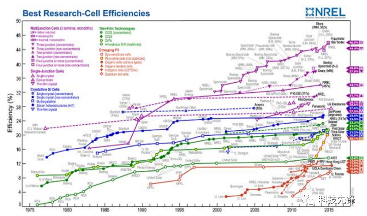
Conversion efficiency is the most important indicator to measure the performance of solar cells, and the highest certified battery conversion efficiency has reached 20.1% (Figure 3). The bottleneck that limits the improvement of solar cell conversion efficiency is that most of the energy of incident light is lost by reflection or transmission, and only light with an energy gap close to the light-absorbing layer material can be absorbed and converted into electrical energy. Therefore, the key to improving battery conversion efficiency lies in improving the energy band structure of the battery. In addition to adjusting the energy gap by adjusting the ionic groups in the perovskite material mentioned above, the preparation of multi-junction solar cells with different energy gaps is also one of the important research directions in this field.

Figure 3 Conversion efficiency data of various solar cells given by the National Renewable Energy Laboratory (NREL)
In addition, reducing the recombination of electrons and holes in the transport process to increase the transport rate is also an important way to improve the conversion efficiency.
(Ⅰ) Interface control. It can be seen from the working mechanism of the perovskite cell that the improvement of the conversion efficiency of the perovskite solar cell depends not only on the light absorption capacity, but also on the carrier transmission rate in the perovskite structure.
(Ⅱ) Improve the preparation process of perovskite batteries. As a new type of thin-film solar cell, the perovskite solar cell has a preparation process similar to other thin-film cells, such as spin coating method (solution spin coating method), vacuum evaporation method (gas phase method), etc. Regardless of the preparation method, the goal is to prepare high-purity, low-defect, high-coverage, and dense perovskite layer films and transport layer films. The essence is to improve the electrical contact between different layer structures, reduce defect density, and reduce load. The loss of currents in the transmission process, thereby achieving high battery conversion efficiency.
(Ⅲ) Try new materials and new battery structures. At present, the most commonly used materials for perovskite solar cells are CH3NH3PbI3 as the light absorption layer, TiO2 as the electron transport layer, and spiro-OMeTAD as the solid hole transport layer. The initial conversion efficiency reached 8.3%. In order to further improve the conversion efficiency of solar cells and highlight the advantages of perovskite materials, people have begun to use new materials in different structures of solar cells or design new cell structures, hoping to achieve breakthroughs.
Generally speaking, whether it is the use of new materials or the improvement of new device structures, although various methods have achieved better cell conversion efficiency, it is still slightly lower than that of traditional perovskite solar cells. From the perspectives of cost, stability, and environmental friendliness, they all have high research value.
Improve solar cell stability
Organometal halide perovskite materials have poor stability in humid environments and light conditions, and are prone to decomposition, which will cause cell efficiency to decrease or even fail. Therefore, in addition to continuously improving conversion efficiency, many current researches are also committed to improving the stability of solar cells Sex. The stability of perovskite batteries is restricted by various environmental factors such as temperature and humidity. There are two ways to improve the stability of perovskite batteries: one is to improve the stability of the perovskite material itself, and the other is to find a suitable transport layer material to isolate the battery from the environment and inhibit the decomposition of the perovskite material.
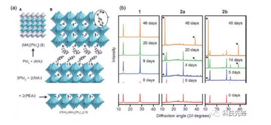
In the former method, Smith et al. used a two-dimensional hybrid perovskite material (PEA)2(MA)2[Pb3I10] (PEA=C6H5(CH2)2NH3+, MA=CH3NH3+) as the absorbent material (structure such as Figure 4), the structure can be formed by spin-coating deposition and does not require high-temperature annealing. Compared with the ordinary three-dimensional perovskite material (MA) [PbI3], the two-dimensional perovskite battery is placed in a humid environment at room temperature for 46 days without causing significant performance degradation and has good stability. However, the selection of atoms/atom groups that can replace each component in ABX3 is currently limited, and related research reports are relatively few. In recent years, more research has focused on the latter, that is, looking for suitable transport layer materials.

Figure 4 (Online version color) Improvement and stability enhancement of perovskite materials.
(A) Schematic diagram of two crystal structures, where A and B are three-dimensional materials (MA) [PbI3] and two-dimensional materials (PEA) 2 (MA) 2 [Pb3I10] respectively;
(B) XRD spectra of different films after the same time in a humid environment, of which 1, 2a, 2b are two-dimensional material films, three-dimensional material films with poor spin coating quality, and three-dimensional material films with good spin coating quality
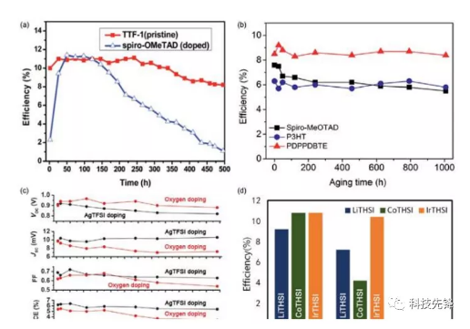
In the second method, researchers are dedicated to finding better hole transport materials to improve the stability of perovskite solar cells. Good hole transport materials can make excitons have a longer life and quantum yield, and extend the life of the battery. The hole transport material commonly used in perovskite batteries is p-type doped spiro-OMeTAD. There are two types of ideas for improving material stability by changing hole transport materials: the first is to replace the original hole material with other materials; the other is to add additives to the hole material or replace the original p-type additives. The effect of two types of methods to improve stability is shown in Figure 5.

Figure 5 (online color) Different methods to improve the stability of perovskite solar cells.
(A) Comparison of the stability of two batteries using tetrathiafulvalene derivatives (TTF-1) and cyclodifluorene (spiro-OMeTAD) as hole transport materials;
(B) The stability comparison between the PDPPDBTE battery and the raw material battery;
(C) The stability of the battery after using different dopants;
(D) The battery efficiency changes of different XTHSIs after 3 months (where X stands for metal elements (such as Li, Co, Ir), and THIS stands for bis(acyltrifluoromethane)imide))
In the second type of method, the introduction of p-type additives can increase the carrier concentration, thereby reducing the series resistance and the charge transfer resistance at the interface. The current ideal dopant is LiTFSI (lithium-based di(acyl trifluoromethane) imide). However, in an oxygen-containing environment, oxygen will consume lithium ions on the hole transport layer and the surface of TiO2, which will reduce the photocurrent, increase the resistance, and reduce the stability of the battery. Therefore, finding better additives can not only improve the efficiency. , You can further improve the stability. The use of other elements to replace metal Li is one of the current research hotspots.
Realize the environmental friendliness of perovskite solar cells
Due to the environmental unfriendliness of lead-containing materials, researchers are striving to achieve lead-free, but the corresponding reduction in battery conversion efficiency will result. The most direct method is to use the same family elements (such as Sn) to replace the Pb element. In MAXI3 material, the energy gap of CH3NH3SnI3 is only 1.3 eV, which is much lower than the 1.55 eV of CH3NH3PbI3, which can make the absorption spectrum red shift. CsSnI3 is used as a light absorbing material, and SnF2 is added as an additive to reduce defect density, increase carrier concentration, and improve battery efficiency. The absorption spectra of these two alternative absorbing materials have a significant red shift and can absorb incident light in a wider band.
From the perspective of solving environmental pollution without sacrificing battery conversion efficiency, Chen et al. proposed another idea, which is to recycle car batteries to provide a source of lead. Because the lead source in automobile batteries has the same material characteristics (such as crystal structure, morphology, light absorption and photovoltaic performance) and photoelectric properties, it not only provides the lead source required for the preparation of perovskite materials, but also solves the problem of waste Lead batteries can’t handle problems properly, so they have certain practical application value.
in conclusion
Perovskite solar cells also have some problems that need to be broken. First of all, people mostly focus on improving materials and preparation methods from different angles to improve the conversion efficiency of batteries, but a complete theoretical model has not been established.


 In recent years, the research on perovskite solar cells has continuously set new records for photoelectric conversion efficiency, which currently exceeds 22%.


